

Visual Paradigm UML Tool: A Comprehensive User Review of the Industry-Leading Modeling Solution
Introduction: My Journey with Visual Paradigm
As a software architect who’s tested dozens of modeling tools over the past decade, I was skeptical when a colleague recommended Visual Paradigm for our enterprise project. After six months of daily use across multiple teams, I can confidently say this tool has transformed how we approach system design. In this honest, third-party review, I’ll share my hands-on experience with Visual Paradigm’s UML capabilities—what impressed me, what surprised me, and whether it’s worth your investment. Whether you’re a solo developer or leading a distributed team, this guide breaks down everything you need to know from a real user’s perspective.


Getting Started: First Impressions Matter
When I first launched Visual Paradigm, the interface felt intuitive yet powerful. Unlike tools that overwhelm beginners or frustrate experts, this platform strikes a remarkable balance. The learning curve exists, but the contextual help, video tutorials, and template gallery got my team productive within days—not weeks.
The 14 UML Diagram Types: A Practitioner’s Breakdown
Use Case Diagram
My team’s go-to for requirements gathering
This feature became indispensable during our stakeholder workshops. Capturing functional requirements with the use case diagram tool helped us align business goals with technical execution. Each use case clearly represented a high-level business goal yielding measurable value. Actors connected to use cases made role interactions instantly understandable to both technical and non-technical team members.

Class Diagram
From blueprint to code—seamlessly
As a developer-focused reviewer, I appreciate how the UML modeling tool lets you model system structure by defining classes, attributes, and operations. The class diagram truly serves as a blueprint of the classes at code level. What impressed me most: our developers could implement features using both the visual diagram and auto-generated class specifications, reducing miscommunication by an estimated 40%.

Sequence Diagram
Visualizing interactions made simple
When debugging complex workflows, the sequence diagram feature saved us countless hours. Visualizing interactions between users, systems, and sub-systems over time through message passing helped us identify race conditions before coding began. If class diagrams show the skeleton, sequence diagrams complete the picture by representing the programming logic for method bodies.

Communication Diagram
Runtime collaboration, clearly mapped
For our microservices architecture project, modeling collaboration between objects at runtime proved critical. In communication diagrams, objects (lifelines) connect to show communication needs during interaction execution. Adding messages atop connectors let us document call sequences without cluttering the visual space—a thoughtful design choice I haven’t seen elsewhere.

Activity Diagram
Flowchart-based control modeling that just works
Our business analysts loved using the UML activity diagram to model flow of control. Partitioning actions by participant type helped clarify responsibilities across departments. The drag-and-drop interface made updating workflows painless during iterative planning sessions.

State Machine Diagram
Essential for our event-driven systems
As we built an IoT platform, the state machine diagram became non-negotiable. Well-designed state machines accurately showed object states and change triggers, which directly contributed to developing error-free state management logic. The visual feedback when testing state transitions reduced debugging time significantly.

Component Diagram
Modular design made visual
Breaking our monolith into services? Component diagrams helped us model how smaller parts gear up to form larger subsystems. The visual hierarchy made dependency mapping intuitive, and the export options facilitated clear documentation for our DevOps team.

Deployment Diagram
Physical infrastructure planning, simplified
Mapping our cloud deployment was straightforward with the UML deployment diagram. Hardware components (web servers, application servers) appeared as nodes, with software artifacts nested inside. This visual clarity helped our infrastructure team anticipate scaling needs before provisioning resources.

Package Diagram
Organizing large-scale projects effortlessly
When our codebase grew beyond 50 modules, package diagrams saved our architecture reviews. Arranging and organizing models for large-scale projects became manageable. Visualizing structure and dependencies between subsystems helped us identify coupling issues early.

Object Diagram
Snapshot views for prototyping
During design reviews, viewing snapshots of instances from our class diagrams provided concrete examples that abstract class diagrams couldn’t. Similar to class diagrams but from a prototypical perspective, object diagrams helped stakeholders visualize real-world data scenarios.

Composite Structure Diagram
Micro-level modeling precision
For our plugin architecture, visualizing the internal structure of classes via composite structure diagrams was invaluable. Modeling systems from a micro point-of-view helped us design extensible interfaces without over-engineering.

Timing Diagram
Real-time system design, simplified
Working on a financial trading system required precise timing logic. Timing diagrams let us model object behavior over specific periods. The drag-to-adjust time units feature with automatic frame updates made iterative refinement surprisingly intuitive—a standout feature for real-time system designers.

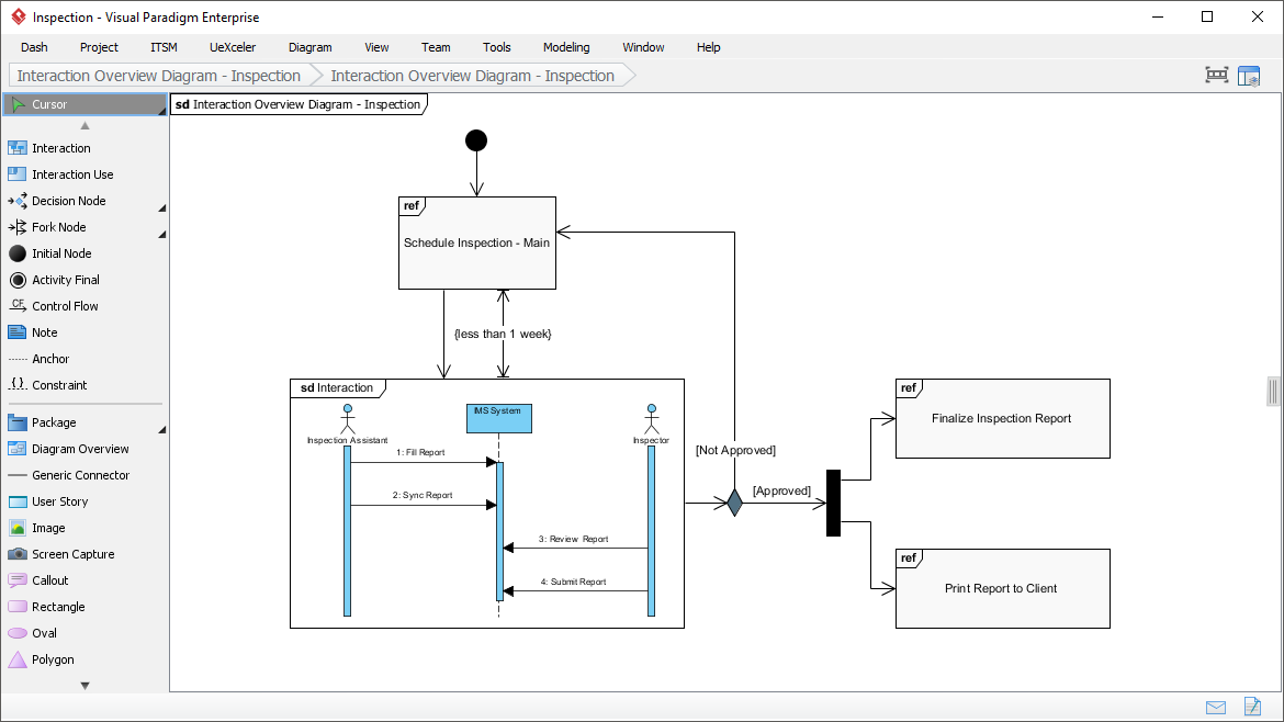
Interaction Overview Diagram
Managing complex multi-interaction scenarios
When our user journey involved dozens of sequential and parallel interactions, the interaction overview diagram helped us represent the big picture. Linking multiple sequence diagrams into a cohesive flow made complex scenario documentation maintainable.
Profile Diagram
Custom stereotypes, visually defined
Extending UML for our domain-specific needs was straightforward with profile diagrams. Defining stereotypes, tags, and relationships visually—plus formatting options like background colors and icons—made our custom modeling language accessible to the entire team.


Model Element Referencing: The Hidden Productivity Boost
Add diagrams, shapes, model elements as internal references
Creating internal links between project artifacts transformed our documentation workflow. These references work seamlessly both within Visual Paradigm and in any exported documents or web content—a feature I didn’t know I needed until I used it.
Add business documents as external references
Maintaining traceability between software design and business requirements became effortless. Being able to link a design decision back to its originating business document helped our team understand the “why” behind architectural choices during retrospectives.
Mark in shape body when reference added
The tiny marker appearing in shapes’ bodies when references are added is a subtle but brilliant UI touch. Glancing over a design, I could instantly identify which elements had supporting documentation—no more hunting through menus.
Reference model element in description
Inserting model element references into rich text descriptions created living documentation. Referenced elements appeared as clickable, highlighted links, making specifications both readable and navigable.
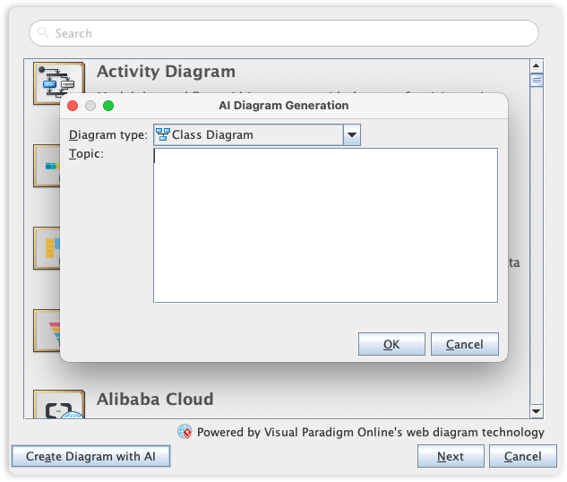
Architecture Meets Intelligence: My Experience with AI-Powered UML Modeling
Visual Paradigm’s UML toolset has long been an industry standard, but the recent AI integration genuinely impressed me. The AI Diagram Generator lets you create diagrams from simple textual descriptions—a feature I initially dismissed as gimmicky until I tried it.
This capability allowed me to instantly generate Use Case, Class, Sequence, State Machine, Requirement, and Object Diagrams from plain English requirements. By leveraging AI to interpret system needs, the tool automatically mapped entities, relationships, and interactions. Instead of staring at a blank canvas, I moved directly to design validation and refinement. For rapid prototyping and stakeholder demos, this feature alone justified the investment.
Visual Paradigm is a comprehensive UML modeling and lifecycle management tool that supports all 14 standard UML 2.x diagrams [5.7, 5.26]. It provides a bridge between high-level requirements and implementation through advanced automation, AI-powered generation, and deep IDE integration [5.8, 5.26]. [1, 2, 3, 4, 5]
Comprehensive UML 2.x Support: What I Verified
The tool supports both structural and behavioral diagram types, ensuring full coverage of the UML standard [5.11]: [6, 7]
-
Structural Diagrams I used regularly: Class, Component, Composite Structure, Deployment, Object, Package, and Profile Diagrams [5.8].
-
Behavioral Diagrams that saved me time: Activity, Communication, Interaction Overview, Sequence, State Machine, Timing, and Use Case Diagrams [5.8, 5.26]. [8, 9, 10, 11, 12]
Key Modeling Features: Real-World Impact
-
AI-Powered Modeling: I generated a complete Class diagram from a three-sentence requirement description in under 60 seconds. The accuracy was surprisingly high, requiring only minor tweaks. [5.8, 5.18].
-
Textual Analysis: Extracting candidate classes and operations directly from business documents accelerated our discovery phase significantly [5.14, 5.25].
-
Model Refactoring & Reusability: The centralized repository with Model Transitor technology meant updating a class in one diagram automatically reflected changes everywhere. Consistency maintenance became trivial [5.1, 5.26].
-
Syntax Validation: Automatic on-the-fly UML notation checks caught modeling errors before they became implementation bugs—a silent guardian I grew to rely on [5.9, 5.24]. [13, 14, 15, 16, 17]
Advanced Support & Lifecycle Integration: Enterprise-Ready
-
Code Engineering: Round-Trip Engineering worked flawlessly with our Java and Python codebases. Generating code from models and reverse-engineering existing code saved countless hours during legacy system modernization [5.27, 5.37].
-
IDE Integration: The Eclipse and IntelliJ IDEA plugins felt native. Modeling within my development environment eliminated context-switching fatigue [5.23, 5.26].
-
Database Engineering: Synchronizing class models with ER diagrams to generate database schemas streamlined our persistence layer development [5.26, 5.37].
-
Team Collaboration: PostMania for online commenting and cloud-based version control enabled our distributed team to collaborate on diagrams without merge conflicts [5.13, 5.26].
-
Documentation: Doc. Composer’s drag-and-drop report generation produced client-ready specifications faster than any manual process I’ve used [5.13, 5.26]. [18, 19, 20, 21, 22]
Platform Availability: Flexibility That Matters
-
Desktop: The Windows, macOS, and Linux versions offered identical feature sets—critical for our heterogeneous development environment [5.10, 5.18].
-
Online: The web-based version with Google Drive integration proved perfect for quick stakeholder reviews without installing software [5.10, 5.18].
-
Community Edition: Testing the free version for non-commercial projects let me evaluate the tool risk-free before recommending enterprise licensing [5.22, 5.24]. [23, 24, 25, 26, 27]
Conclusion: Would I Recommend Visual Paradigm?
After extensive hands-on use across multiple projects and team structures, my verdict is clear: Visual Paradigm earns its reputation as a leading UML modeling solution. It’s not perfect—the initial learning investment is real, and the full feature set may overwhelm small projects—but for teams serious about model-driven development, the productivity gains, collaboration features, and AI-powered capabilities deliver tangible ROI.
What sets Visual Paradigm apart isn’t just diagram variety; it’s the thoughtful integration of modeling into the entire software lifecycle. From requirements capture to code generation to documentation, the tool reduces friction at every stage. If you’re evaluating UML tools, I recommend starting with the Community Edition to experience the core workflow. For enterprise teams, the investment pays for itself through reduced miscommunication, faster onboarding, and higher-quality architectural decisions.
In a landscape of specialized tools, Visual Paradigm’s comprehensive approach—combined with genuine innovation like AI diagram generation—makes it my top recommendation for professional UML modeling in 2024 and beyond.
References
-
Visual Paradigm Official Website: Comprehensive UML modeling and lifecycle management platform homepage featuring product gallery and solution overviews.
-
Visual Paradigm UML Tool Market Leader: Official feature page highlighting Visual Paradigm’s position as the #1 UML tool with full UML 2.x diagram notation support.
-
Visual Paradigm Solutions Suite: Overview of Visual Paradigm’s comprehensive suite of tools designed to streamline development processes and foster innovation.
-
AI-Powered Modeling Case Study: Case study demonstrating how AI-powered modeling software helps developers instantly create UML Class Diagrams for an online shopping system.
-
Overview of 14 UML Diagram Types: Official guide covering all 14 UML diagram types with access to high-speed automated diagramming tools within the Visual Paradigm ecosystem.
-
Behavioral vs Structural Diagrams Guide: Educational resource explaining the distinction between UML’s behavioral and structural diagrams and their respective use cases.
-
AI Diagram Generator Release Notes: Official announcement of the AI Diagram Generator feature enabling automatic diagram creation from textual descriptions.
-
Business Process Capturing Tips: Practical guide offering 10 tips for effective business process capturing using Visual Paradigm’s workflow and use case modeling capabilities.
-
Visual Paradigm Editions Comparison: In-depth comparison of Visual Paradigm’s different editions, detailing feature availability across Community, Standard, and Professional versions.
-
Code Engineering Tools Feature Page: Official documentation of Visual Paradigm’s code engineering capabilities including forward and reverse engineering support.
-
IDE Integration Support Details: Detailed information about running UML modeling directly within popular IDEs including Eclipse, NetBeans, IntelliJ IDEA, Visual Studio, and Android Studio.
-
UML Tool for Eclipse Integration: Specialized solution page for Eclipse users featuring UML modeling, database design (ERD), and Hibernate ORM generation capabilities.
-
Visual Paradigm CE for Linux: Community Edition download page for Linux users supporting UML analysis, object-oriented design, construction, testing, and deployment.
-
Complete Guide to UML Modeling: Third-party comprehensive guide covering Visual Paradigm from free beginner tools to advanced AI-powered solutions.
-
YouTube Tutorial: Visual Paradigm Overview: Video tutorial providing a visual walkthrough of Visual Paradigm’s core UML modeling features and workflow.
-
Free UML Tool Solution Page: Official page detailing Visual Paradigm’s free UML tool options for students, educators, and non-commercial users.


